OSI and TCP/IP Models: A Beginner’s Guide
The OSI model and the TCP/IP model are two ways of describing how data gets from one computer to another. They are both “layered” models: the job of moving data is split into stages, each stage does one thing and only talks to the stages directly above and below it. You will meet both in courses and interviews, and they genuinely help when something breaks, because thinking in layers tells you where to look first. This guide explains both models, how they map to each other, and how to use them when troubleshooting.
Why layers?
Sending an email involves an enormous number of separate problems: turning bits into electrical or radio signals, addressing, choosing routes, making sure nothing is lost, and presenting the data to an application. Layering splits these into manageable pieces. Each layer can be improved or replaced without changing the others: your browser does not care whether the data travels over Wi-Fi or Ethernet, and the Wi-Fi adapter does not care what the browser is asking for.
The OSI model: seven layers
The OSI (Open Systems Interconnection) model was published by the ISO and the ITU-T as a reference framework. It has seven layers, usually numbered from the bottom:
| # | Layer | Job | Examples | Data unit |
|---|---|---|---|---|
| 7 | Application | Services that applications use directly | HTTP, DNS, SMTP, SSH | Data |
| 6 | Presentation | Data format, encoding, encryption | TLS (often placed here), character sets, JPEG | Data |
| 5 | Session | Opening, managing and closing conversations | Session handling in RPC and similar | Data |
| 4 | Transport | End-to-end delivery, ports, reliability | TCP, UDP | Segment / datagram |
| 3 | Network | Logical addressing and routing between networks | IP, ICMP, routers | Packet |
| 2 | Data link | Delivery on one local network, MAC addresses | Ethernet, Wi-Fi, switches | Frame |
| 1 | Physical | Bits as signals on a medium | Cables, radio, fibre, hubs | Bits |
A popular memory aid, from top to bottom, is “All People Seem To Need Data Processing”; from the bottom up, “Please Do Not Throw Sausage Pizza Away”.
The TCP/IP model: four layers
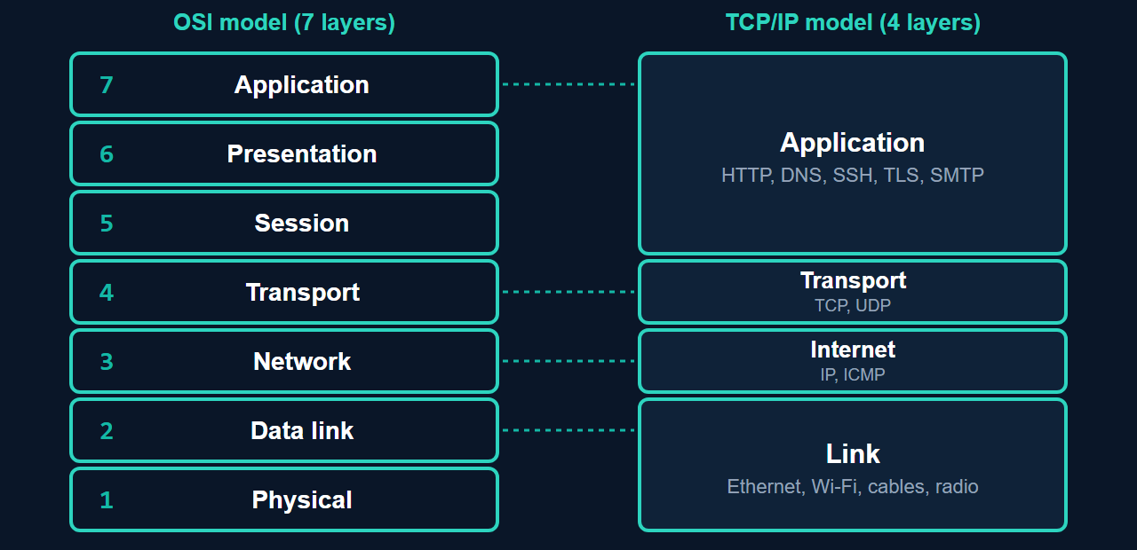
The TCP/IP model describes how the internet’s protocols are actually organised. It is defined in RFC 1122 with four layers, though many textbooks split the bottom layer in two and show five:
- Application: everything above the transport layer, including HTTP, DNS, SSH, TLS and email protocols.
- Transport: TCP (reliable, ordered delivery) and UDP (simple datagrams with no delivery or ordering guarantees), both using port numbers to identify the application.
- Internet: IP addressing and routing, plus ICMP (used by ping).
- Link: how data moves on the local network: Ethernet, Wi-Fi and the physical connection.
How the two compare
OSI is a teaching and reference model with clean layer boundaries. TCP/IP is the model the internet was built on and is closer to how real software is structured. The top three OSI layers (application, presentation, session) roughly collapse into TCP/IP’s single application layer, and OSI’s physical and data link layers correspond to TCP/IP’s link layer. In practice, people use OSI numbering as a shared vocabulary (“a layer 2 problem”, “a layer 7 firewall”) and TCP/IP to describe real protocols.
Encapsulation: how data travels down and up
When an application sends data, each layer typically wraps it with its own header (and sometimes a trailer), a process called encapsulation. Your browser’s request is given a TCP header (with ports), then an IP header (with source and destination IP addresses), then an Ethernet or Wi-Fi header (with MAC addresses), and finally sent as bits. The receiver reverses the process, each layer stripping its own header and passing the rest upward. This is why the data unit changes name as it goes down: data, segment, packet, frame, bits.
A subtle point: MAC addresses are rewritten at every router hop, because each link delivers the frame to the next device (switches leave them unchanged). IP addresses stay the same from end to end (apart from NAT), because they name the ultimate source and destination.
Using layers to troubleshoot
Work from the bottom up and rule out one layer at a time:
- Physical: Is the cable plugged in, the link light on, the Wi-Fi connected?
- Data link: Is the device on the right VLAN or network? Is there a MAC or switch problem?
- Network: Does the device have a valid IP address, and can it
pingits gateway and a remote address? A169.254.x.xaddress points to a DHCP problem. - Transport: Is the port open?
ss -ltnon Linux ornetstat -anon Windows shows listening ports, and a firewall may be blocking the connection. - Application: Does the service itself respond?
curl -I https://example.comshows whether the web server answers correctly.
The same thinking applies to server problems: Linux networking basics for sysadmins and port already in use put these layers to work.
Common questions
Which layer is TLS or HTTPS?
It does not fit cleanly. TLS is often described at layer 6 (presentation) in OSI, but in the TCP/IP model it is simply part of the application layer, running over TCP.
Is a switch layer 2 or layer 3?
A basic switch works at layer 2, using MAC addresses. A layer 3 switch can also route between IP subnets. See networking devices from hubs and switches to routers and modems.
Do I need to memorise the OSI layers?
For exams, yes. In daily work, it is enough to know the order and which layer each of the common tools and devices belongs to.